RSPAN
Remote Switch Port Analyzer (RSPAN) provides remote monitoring traffic from source ports distributed over multiple switches. It supports source ports, source VLANs, and destination ports on different switches.
In this method, appliance is in the same Layer 2 (L2) network but cannot be connected directly to the switch.
In all the situations mentioned below, RSPAN can be used. RSPAN method centralizes the mirror traffic from one/multiple Layer 2 switches by mirroring the traffic from the source ports of an RSPAN session to a VLAN that is dedicated for the RSPAN session. This VLAN is then trunked to the other switches allowing the RSPAN session traffic to be transported across multiple switches. On the switch that contains the destination port for the session, traffic from the RSPAN session VLAN is simply mirrored out to the destination port where Network Passive Sensor sniffing interface is connected.
- Network Passive Sensor is in the same L2 network as the switch and appliance is not physically co-located with the switch OR
- Network Passive Sensor is in the same L2 network as the switch and network has many Layer 2 switches. Then it may not be possible to do local mirroring on each Layer 2 switch and deploy multiple passive sensors connecting to SPAN port of each Layer 2 switch. OR
- Network Passive Sensor is in the same L2 network as the switch and Local SPAN is not possible because all ports on a switch are occupied.
For RSPAN deployment the user must know the CPU utilization of the network switch before-hand. If the switches are already utilizing high CPU then enabling RSPAN may cause the switch to drop packets.
If your network has many Layer 2 switches then it may not be possible to do local mirroring on each Layer 2 switch and deploy multiple passive sensors connecting to SPAN port of each Layer 2 switch. To handle this situation, you need to use RSPAN method to centralize the mirror traffic from various Layer 2 switches. RSPAN works by mirroring the traffic from the source ports of an RSPAN session to a VLAN that is dedicated for the RSPAN session. This VLAN is then trunked to the other switches allowing the RSPAN session traffic to be transported across multiple switches. On the switch that contains the destination port for the session, traffic from the RSPAN session VLAN is simply mirrored out to the destination port where Network Passive Sensor sniffing interface is connected.
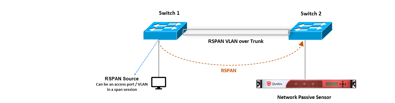
The above diagram shows RSPAN connectivity for Physical Appliance, however the same connectivity works for Virtual Appliance.
Sample RSPAN Configurations
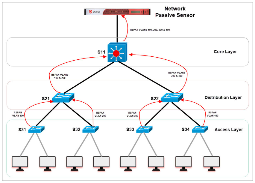
In this section, you’ll understand various configurations required on core, distribution, and access layer.
Following diagram illustrates how the mirrored traffic (red arrows) flows from Access layer to distribution layer and from distribution layer to core switch.
Sample Configuration on S31
This configuration helps to mirror the traffic on access layer (user connected) switches.
- Create RSPAN VLAN
vlan 100name rspan_vlan_100remote-spanexit - Configure S31 uplink connected to S21 to allow RSPAN VLAN
interface GigabitEthernet1/0/15switchport mode trunkswitchport trunk allowed vlan add 100no shutdown - Mirror traffic of users vlan (for example - vlan 31) connected to configured RSPAN VLAN (vlan 100) on the switch
monitor session 1 source vlan 31 rxmonitor session 1 destination remote vlan 100
Sample Configuration on S21
This configuration helps to create RSPAN VLAN and allows RSPAN traffic to pass through trunk ports for distribution layer switches.
- Create RSPAN VLAN
vlan 100name rspan_vlan_100 remote-spanexitvlan 200name rspan_vlan_200 remote-spanexit - Configure S21 interface connected to S31 to allow RSPAN VLAN 100
interface GigabitEthernet1/0/19switchport mode trunkswitchport trunk allowed vlan add 100no shutdown - Configure S21 uplink connected to S11 to allow RSPAN VLAN
interface GigabitEthernet1/0/20switchport mode trunkswitchport trunk allowed vlan add 100, 200no shutdown
Sample Configuration on S11
This configuration helps to create RSPAN VLAN and allows RSPAN traffic to pass through trunk ports for core switches.
- Create RSPAN VLAN
vlan 100name rspan_vlan_100remote-spanexitvlan 200name rspan_vlan_200remote-spanexitvlan 300name rspan_vlan_300remote-spanexitvlan 400name rspan_vlan_400remote-spanexit - Configure S11 interface connected to S21 switch to allow RSPAN VLANs 100,200
interface GigabitEthernet1/0/24switchport mode trunkswitchport trunk allowed vlan add 100, 200no shutdown - Configure S11 interface connected to NPS sniffing port to allow all RSPAN VLANs traffic
interface GigabitEthernet1/0/25switchport mode trunkswitchport trunk allowed vlan add 100, 200,300,400no shutdown
VTP Configurations
VTP configuration can be used to centralize the RSPAN VLAN configurations on Cisco switches.
For example, configure S11 as VTP server and remaining switches as VTP clients. Just adding RSPAN VLANs in S11 will advertise the new VLAN configuration to all other switches which are in VTP client mode and in the same VTP domain.
- Sample VTP server configuration on S11
(config)#vtp domain test(config)#vtp mode server(config)#vtp password mypassword(config)#exit - Sample VTP client configuration on other switches:
(config)#vtp domain test(config)#vtp mode client(config)#vtp password mypassword(config)#exit - Sample config for creating RSPAN VLANs on S11
vlan 100name rspan_vlan_100remote-spanexitvlan 200name rspan_vlan_200remote-spanexitvlan 300name rspan_vlan_300remote-spanexitvlan 400name rspan_vlan_400remote-spanexit - Now all other switches will receive RSPAN VLAN configurations from S11 (vtp server). You can verify the configurations of VLANs using 'show vlan' command.